FEM Simulation for Aerocockpits: Understanding Loads Early

Cycling has been growing in popularity for years: both as a recreational activity and in performance-oriented competition, such as triathlon. To achieve the most aerodynamic riding position possible, so-called aerocockpits are often used. These allow the rider to lower their upper body and rest their forearms, significantly reducing air resistance.
At the same time, aerocockpits are among the most highly stressed components on a road bike. They must be lightweight and stiff, while also remaining safe under real riding conditions. Continuous load in the aero position, asymmetric support, potholes, or braking maneuvers can act on the component simultaneously.
Whether an aerocockpit meets these requirements is determined not only in practical testing but already during the design process. In this context, we collaborated with Martin Brüggemann, who set out to develop the best DIY aerocockpit, on a specific aerocockpit riser and supported the development process through simulation.
The project can be followed at https://aerocockpit.org.
From Riding Position to Real-World Loads
In the aero position, up to 60% of the rider’s body weight is transferred to the aerocockpit via the forearms. This load does not act purely downward; due to geometry and lever arms, it generates significant bending moments.
Additional factors include:
- asymmetric loads caused by uneven posture or one-arm support
- dynamic loads from potholes or road edges
- combined scenarios such as heavy braking while in the aero position
A component may appear well-designed visually, yet still fail under real-world loads if these effects are not taken into account.
Challenges in the Simulation of Aerocockpits
Once the loads were understood, we defined common goals together with Martin. Weight, in particular, is a decisive factor in performance sports. This quickly led to a clear objective: a component that is as dimensionally stable as possible while being optimized for minimal weight.
At this point, a conflict often arises with what is actually implemented in many design processes today. Manually defined load cases, complex representations of asymmetries, time-consuming design iterations, and the need for expert knowledge often result in simulations being used late in the process or only selectively.
This is exactly the critical issue: by that stage, key design decisions have already been made, geometries are fixed, and changes become costly. Simulation is then often used merely for validation, rather than as a tool for design. The true potential of FEM, identifying risks early, optimizing in a targeted way, and enabling well-informed decisions, remains largely untapped.
To fully leverage its benefits, simulation must be applied early, easily, and iteratively: precisely where design is created and decisions are made.
FEM in Dialogue: Describe What Happens – Dr.Q Simulates
That’s why we rely on an AI-supported approach to FEM simulation: one that enables short iteration cycles and aligns with the way users think. Instead of learning to operate complex software, load scenarios can be described in the same way they are understood in real life.
The simulation workflow is intentionally streamlined:
- Upload CAD model
- Select material
- Describe the scenario
With Dr.Q, no technical solver settings need to be defined. Instead, physical boundary conditions are described as they are perceived:
- “A force of 300 newtons acts on surface X.”
- “A torque is applied at one end, while the other end is fixed.”
- “Pressure acts on this surface, while another remains clamped.”
Dr.Q interprets these descriptions and automatically translates them into a complete simulation workflow. This includes defining forces, moments, and constraints. Meshing and computation are carried out automatically, delivering reliable insights into stress distributions and deformations under real-world load conditions in a short time.
In this way, simulation evolves from a specialist tool into an early-stage decision-making instrument.
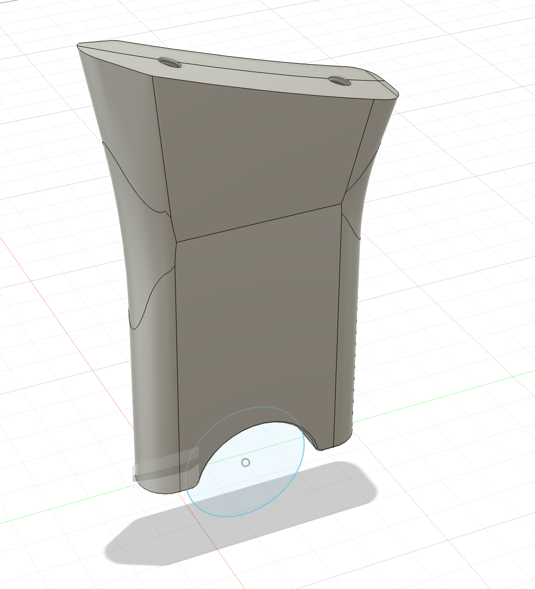
Initial Design Approach: Functional, but Overengineered
The initial aerocockpit design followed a continuous, uniform structure without targeted geometric optimization along actual load paths. This conservative approach ensured that all occurring loads could be reliably absorbed.
Simulation results showed that stresses and deformations were well below critical limits: even under unfavorable load combinations. From a mechanical standpoint, the component was therefore clearly sufficiently dimensioned.
At the same time, it became evident that this safety-driven approach came with high material usage. Even low-stress regions were built solid, resulting in unnecessary weight. Only through analyzing the stress distribution did it become clear where material could be reduced without compromising safety.
This original design was intended for 3D printing. However, it quickly became apparent that the strength of FDM material was insufficient, leading to the decision to switch to a homogeneous metallic component.
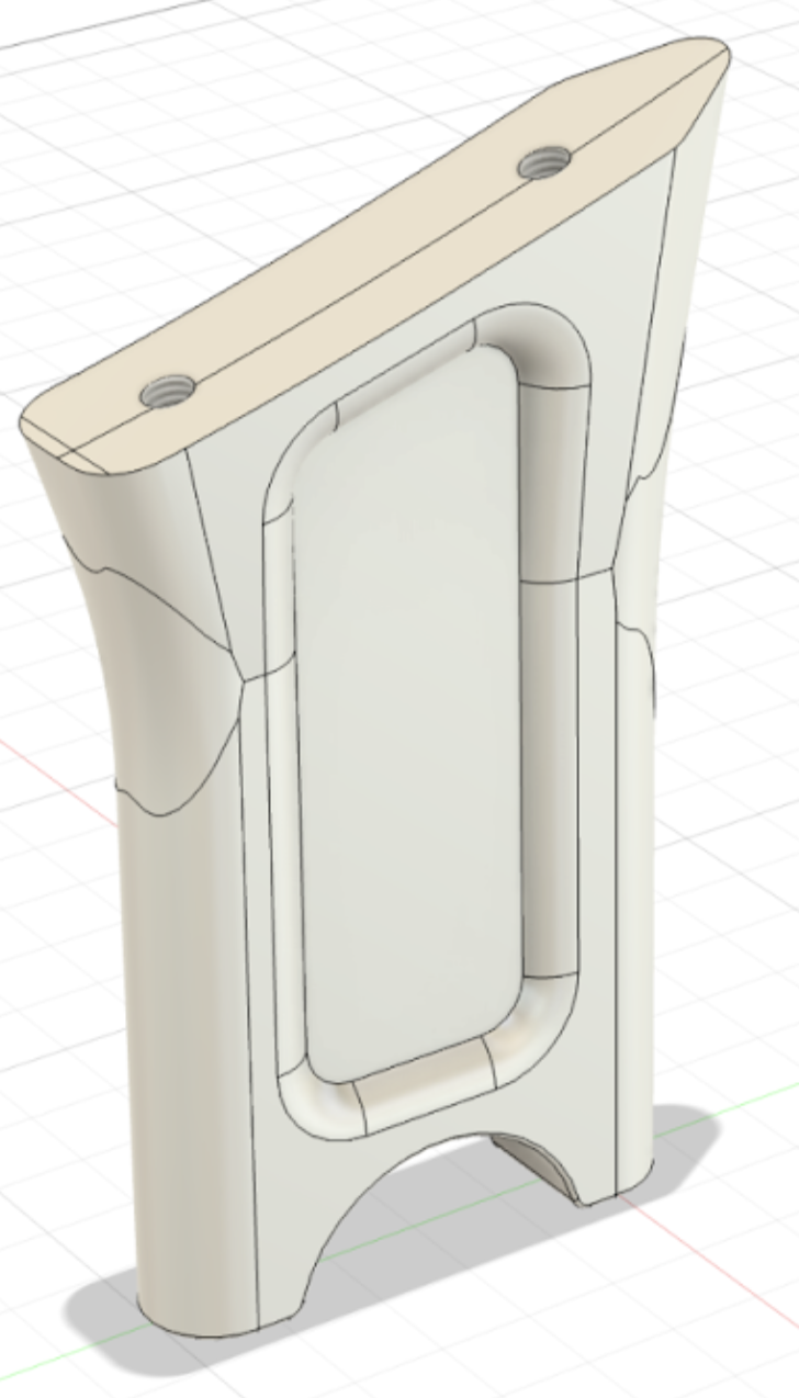
Second Design Approach: Material Where It Matters
In the second design iteration, the cross-section was specifically adapted to the actual load paths. Instead of a continuous solid structure, material was reduced in the region of the neutral axis: where only low stresses occur under bending loads.
The resulting cross-section functionally follows the principle of an I-beam. This geometry uses material more efficiently, as the load-bearing outer regions remain reinforced while the less stressed core is relieved.
FEM simulation confirmed this approach. In the outer, highly stressed areas, stresses increased slightly as expected, but remained well below allowable limits. At the same time, weight was reduced without compromising structural safety.
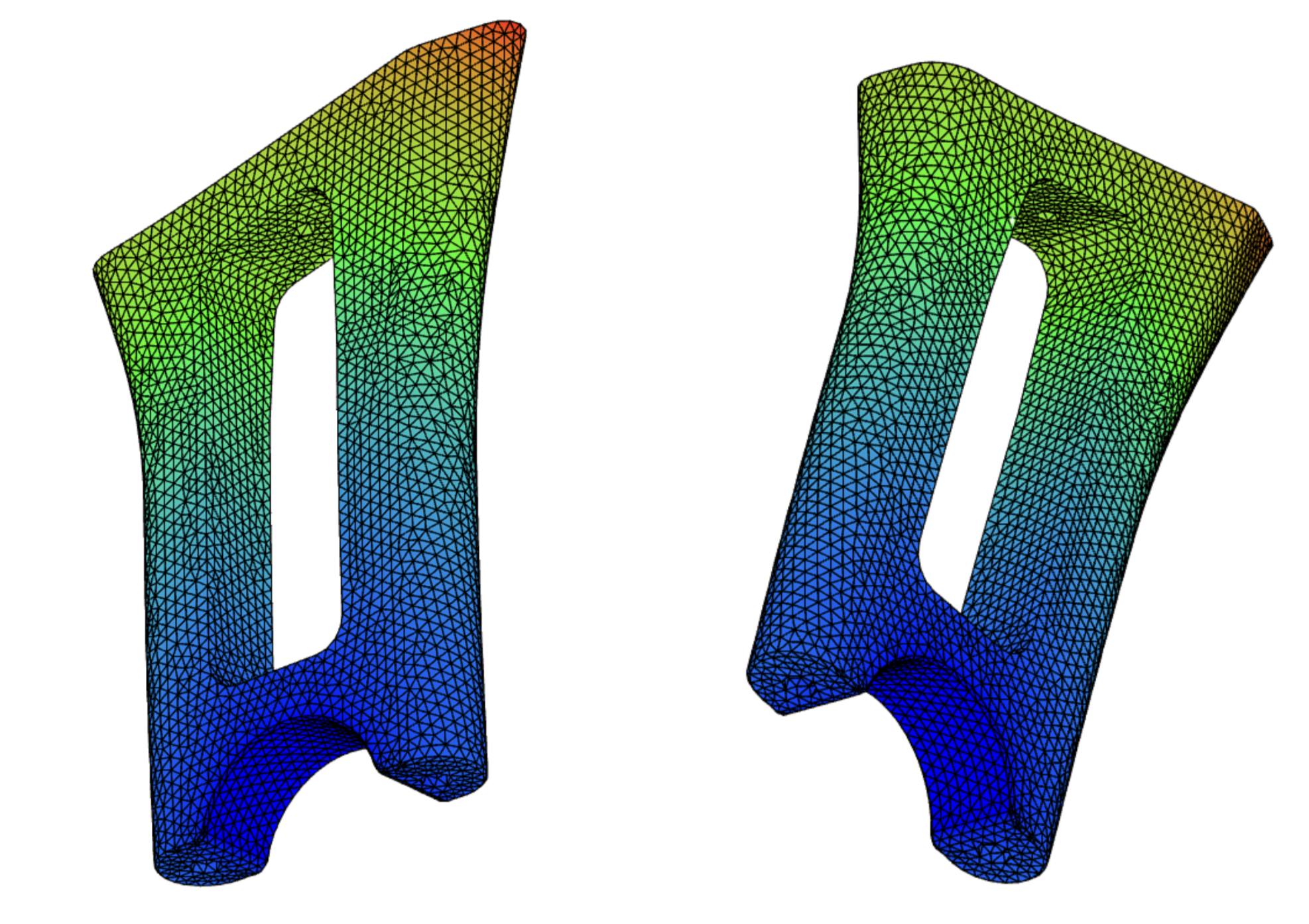
Optimized Design: Consistently Aligned with Load Paths
In the final design, the principle applied in the second iteration was consistently refined. Material in the region of the neutral axis was completely removed, resulting in a cross-section that functionally follows the load paths exactly.
The result is a structure with clearly defined outer regions that are specifically designed to absorb the applied support forces and torques. These zones are geometrically tailored to provide precisely the required cross-section for the local stresses and deformations.
FEM simulation showed that stresses in the outer regions increased further, but still remained well below the maximum allowable limits. At the same time, weight was reduced once again without compromising stiffness or safety.
Model Description & Boundary Conditions of an Example Load Case
Material For the design evaluation, the aluminum alloy 6061 is considered. To assess deformation and strength behavior, the modulus of elasticity and yield strength are used.
Aluminum 6061: Modulus of elasticity ≈ 70 GPa, yield strength ≈ 110 MPa
Load and Boundary Conditions A support force of 250 N and a torque of 30 Nm are applied. The component is fixed at the bottom in the area of a radius. A static load case is considered.
Component Dimensions (W × D × H) 25 × 65 × 110 mm
Simulation Results
Stress Maximum equivalent stress: < 70 MPa Assumed yield strength: 205 MPa Required safety factor: 1.5
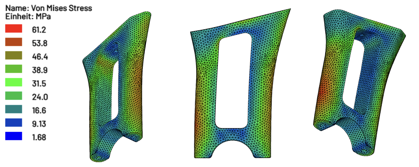
Deformation Maximum deformation: 0.284 mm
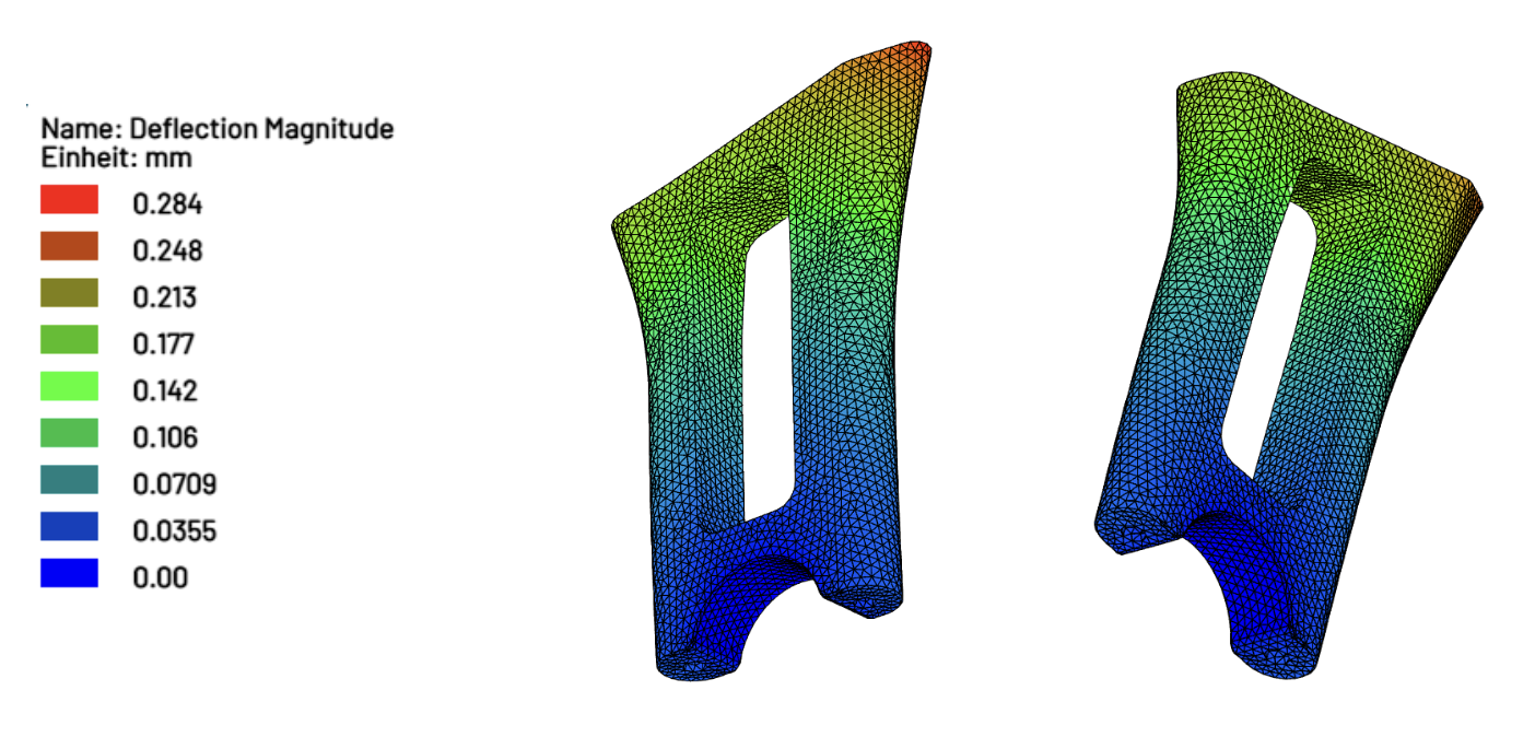
The strength verification is satisfied with a maximum occurring stress of 61.2 MPa, resulting in a safety factor of 1.8. The low deformation indicates high stiffness and adequate serviceability.
Understand Loads Before They Become a Problem
The aerocockpit example demonstrates how crucial it is to consider real load cases early in the development process. Aerocockpits and their risers are components subjected to complex loading conditions, whose requirements arise not from idealized assumptions but from actual riding scenarios.
The step-by-step evolution of the design: from a conservative initial concept to a load-adapted cross-section and finally to consistent material reduction along load paths, clearly illustrates the value FEM simulation can provide when applied early and iteratively.
Those who understand real loads early design better products. Those who can simulate them easily design faster.
Dr.Q makes FEM simulation accessible. As simple as a conversation.
Special thanks to Niclas Holz for working on this project and contributing to this article, as well as to Martin Brüggemann for providing the idea, the 3D files, and for the overall excellent collaboration.